Create a Load Balancer
In the menu, select Load Balancer > Load Balancer, then click Create Load Balancer. The console opens a 5-step wizard:
- Basic Information
- Server Pool & Health Check
- Listener
- Recommended alarm
- Review & Create
The system creates one default Server Pool and one default Listener from the values you provide in the wizard.
Step 1. Basic Information
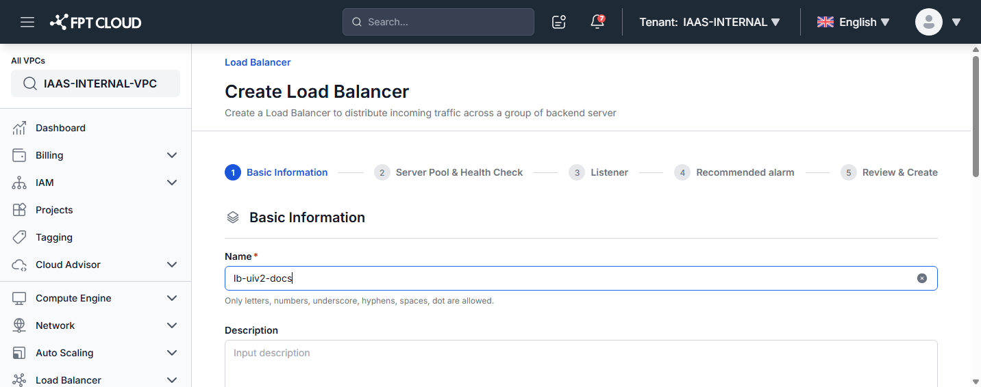
| Field | Description |
|---|---|
| Name | Name of the Load Balancer. Only letters, numbers, underscore, hyphens, spaces, and dot are allowed. Can be changed later. |
| Description | Optional description. |
| Tags | Optional tags applied to the Load Balancer. |
| Scheme | Whether the Load Balancer is reachable from the internet. Internet facing exposes a public IP; Internal is reachable only from inside the VPC. Required, and cannot be changed after the Load Balancer is created. |
| Subnet | The network for the Load Balancer. Select an existing subnet from the list, or leave blank if no specific network planning is required. The Scheme decides the subnet type: Internet facing uses a routed subnet, Internal uses an isolated subnet. |
| Public IP | Shown only when the Scheme is Internet facing. Assign a public IP so the Load Balancer can be reached from the internet. With Internal, the field is hidden and no public IP is assigned. |
| Private IP | Enter a specific private IP within the subnet. Leave blank to assign one automatically. |
Scheme
The Scheme decides whether the Load Balancer is exposed to the internet. Choose it before you fill in the rest of Step 1 — it changes which fields the form shows.
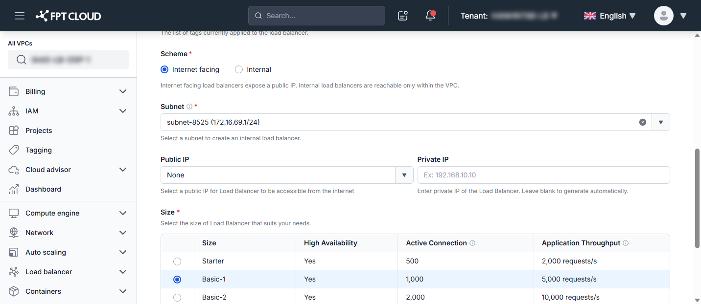
| Scheme | Public IP | Subnet type | External members in the Server Pool |
|---|---|---|---|
| Internet facing | Shown — you assign a public IP | Routed | Allowed |
| Internal | Hidden — no public IP is assigned | Isolated | Not supported |
You can still switch the Scheme while you are on Step 1. If you switch to Internal after adding an external member in Step 2, the wizard keeps your choice and shows a reminder under the Scheme box:
You have external members configured. Go to Step 2 to remove them before continuing.
You cannot move on to Step 3 until those external members are removed.
On VMware-based VPCs, the Scheme field is locked to Internet facing, because every Load Balancer subnet there is routed. Load Balancers created before this field existed are recorded as Internet facing.
Size
Select the package that suits your workload. All packages are high-availability (24/7).
| Size | High Availability | Active Connection | Application Throughput |
|---|---|---|---|
| Starter | Yes | 500 | 2,000 requests/s |
| Basic-1 | Yes | 1,000 | 5,000 requests/s |
| Basic-2 | Yes | 2,000 | 10,000 requests/s |
| Standard | Yes | 4,000 | 20,000 requests/s |
| Advanced-1 | Yes | 6,000 | 30,000 requests/s |
| Advanced-2 | Yes | 8,000 | 40,000 requests/s |
| Premium | Yes | 12,000 | 80,000 requests/s |
Click Next to continue.
Step 2. Server Pool & Health Check
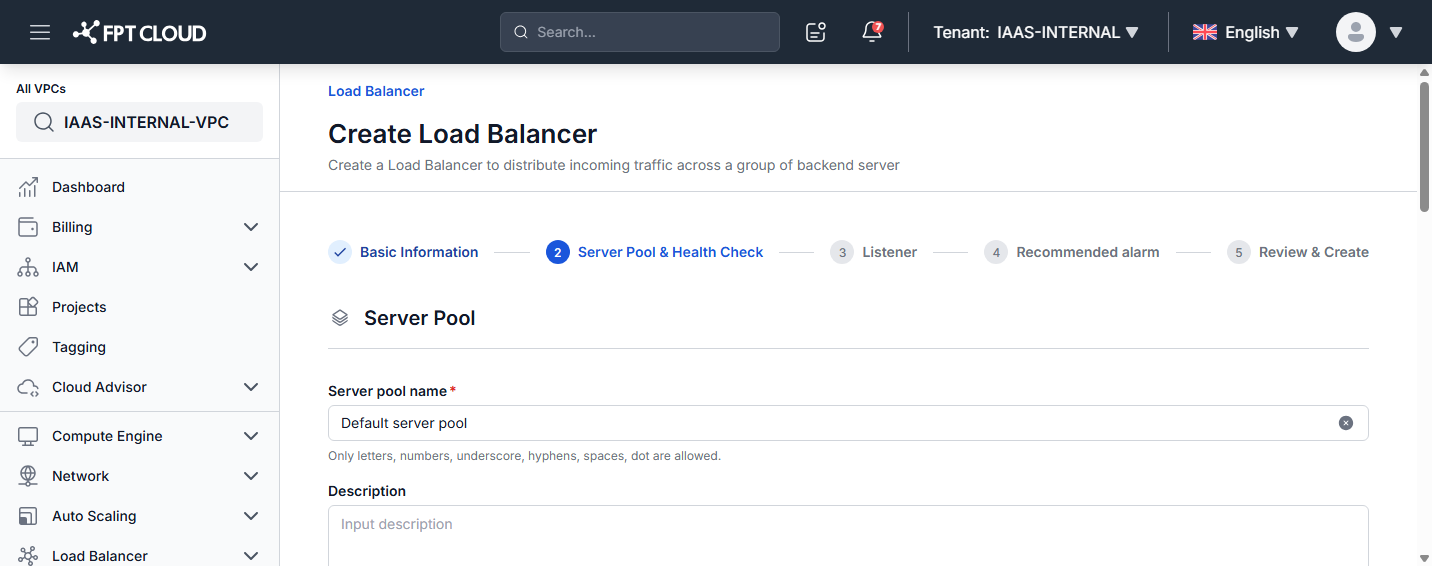
Server Pool
| Field | Description |
|---|---|
| Server pool name | Name of the Server Pool. Default is Default server pool. |
| Description | Optional description. |
| Protocol | Protocol the Server Pool uses (for example, HTTP). |
| TLS | Enable TLS for a secure connection with backend servers. Enable when the Listener uses the TERMINATED_HTTPS protocol. |
| Add server | Add members to the pool — choose instances within the VPC or, on an Internet facing Load Balancer, add an external member (Instance, IP Address, Subnet, Port, Weight). |
An Internal Load Balancer only serves traffic inside the VPC, so it does not accept external members. Add external member is disabled when the Scheme is Internal, and the wizard blocks Next while an external member is still configured:
Internal load balancers do not support external members. Please remove external members to continue.
Either remove the external members, or go back to Step 1 and set the Scheme to Internet facing.
Advanced Settings
| Field | Description |
|---|---|
| Algorithm | Request-distribution algorithm: Round Robin, Least Connection, or Source IP. |
| Sticky session | Keep a client's requests on the same server: None, App Cookie, HTTP Cookie, or Source IP. |
Health Check Settings
| Field | Default | Description |
|---|---|---|
| Protocol | HTTP | Protocol of the health monitor. |
| URL Path | / | Must begin with a forward slash (/). |
| HTTP Method | GET | HTTP method used for health-check requests. |
| Expected Code | 200 | HTTP status codes that declare a member healthy. |
| Max retries down | 3 | 1–10. Failed checks before a member is marked down. |
| Max retries | 3 | 1–10. Successful checks before a member is marked up. |
| Delay (s) | 5 | Time between probes. |
| Timeout (s) | 5 | Maximum time to wait for a probe response. |
Click Next to continue.
Step 3. Listener
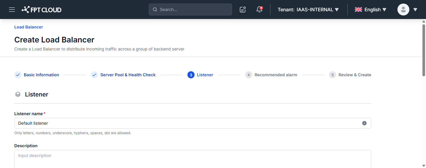
| Field | Description |
|---|---|
| Listener name | Name of the Listener. Default is Default listener. |
| Description | Optional description. |
| Protocol | Protocol the Listener uses to receive requests. |
| Port | Port the Listener listens on (for example, 80). |
| Server pool | The pool that requests are routed to (linked to the pool from Step 2). |
| Allow CIDRs | CIDRs allowed to access this Listener. All other traffic is denied. One CIDR per line. Default 0.0.0.0/0. |
| Deny CIDRs | CIDRs denied access, even if included in the allow list. One CIDR per line. |
| HTTP Headers insertions | Headers inserted into requests to members: X-Forwarded-For, X-Forwarded-Port, X-Forwarded-Proto. |
Advanced Settings
| Field | Default | Description |
|---|---|---|
| Member connect timeout (s) | 5 | Backend member connection timeout. |
| Client data timeout (s) | 50 | Frontend client inactivity timeout. |
| Member data timeout (s) | 50 | Backend member inactivity timeout. |
| TCP inspect timeout (s) | 0 | Time to wait for additional TCP packets for content inspection. |
| Connection limit | -1 | Maximum connections for this Listener. -1 means unlimited. |
Click Next to continue.
Step 4. Recommended alarm
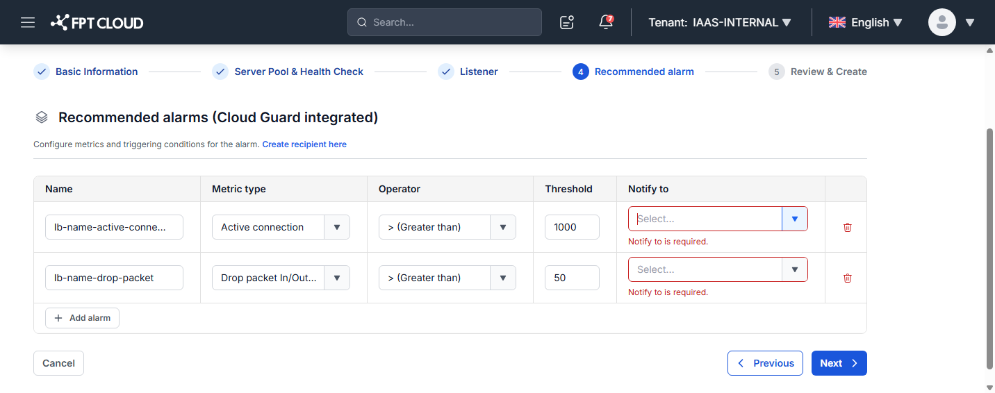
The wizard suggests two Cloud Guard alarms to detect overload conditions:
| Alarm | Metric | Condition |
|---|---|---|
| Active connection | Active connection | Greater than 1,000 |
| Drop packet | Drop packet In/Out per second (packet/s) | Greater than 50 |
For each alarm, select a Notify to recipient (required if you keep the alarm). If you do not have a recipient yet, use Create recipient here to add one (Email, Telegram, Slack, and Teams are supported). Remove an alarm with its delete icon if you do not want it.
Click Next to continue.
Step 5. Review & Create
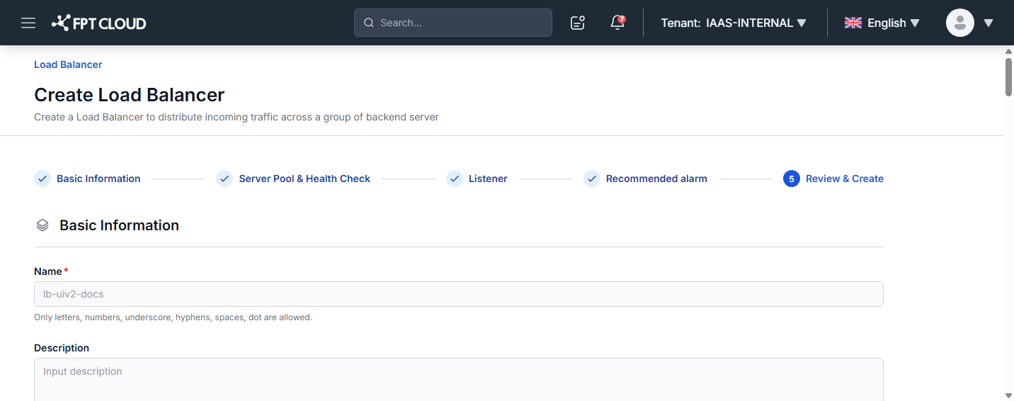
Review the full configuration (read-only). To change anything, click Previous. When ready, click Create Load Balancer.
Check the status
After creation, the console returns to the Load Balancer list. Each Load Balancer, Listener, Server Pool, and Member has its own status.
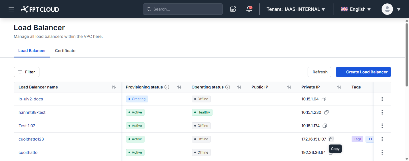
| Object | Provisioning status | Operating status |
|---|---|---|
| Load Balancer | Active: created successfully. Creating: initialising. Updating: being updated. Deleting: being deleted. Error/Pending: an error occurred — contact support. | Healthy: all members healthy. Unhealthy: at least one member unhealthy. Offline: all members unhealthy. No healthcheck: no health check configured. |
| Listener | Same as Load Balancer | N/A |
| Server Pool | Same as Load Balancer | Same as Load Balancer |
| Member | N/A | Healthy: available to receive requests. Unhealthy: unavailable. |
The list also shows the Public IP, Private IP, Tags, Size, and Created at of each Load Balancer.
Load Balancer creation may take a moment. Wait until the provisioning status is Active before continuing.